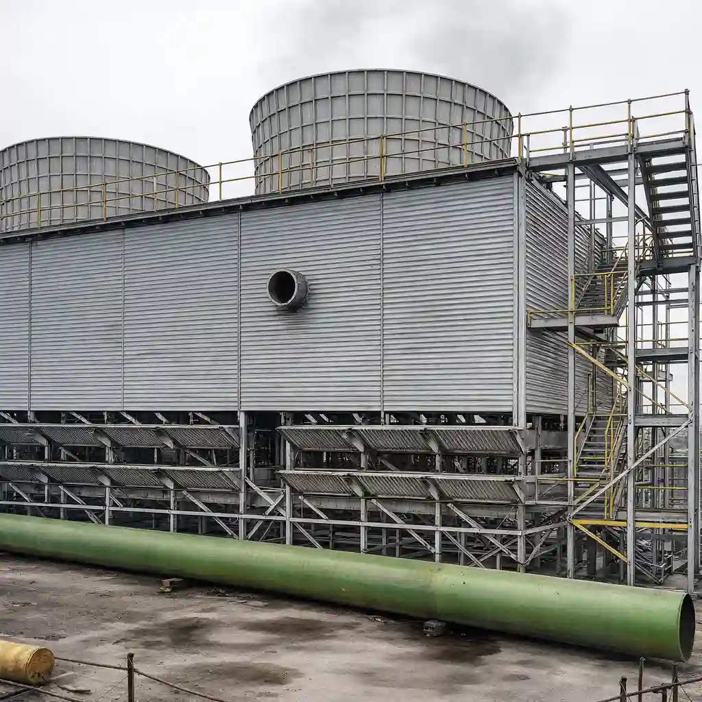
A cooling tower can reject the same process heat while consuming very different amounts of water and electricity. A tower operating with excessive fan speed, low cycles of concentration, fouled fill, or poorly controlled blowdown may appear reliable while quietly increasing utility costs and chemical consumption. For plants with large cooling-water systems, cooling tower optimization is therefore an operating and engineering decision—not simply a maintenance activity.
The objective is to maintain the required cold-water temperature and process reliability with the lowest practical combination of fan power, makeup water, blowdown, chemical treatment, and maintenance cost. Achieving that objective requires a complete view of the cooling-water loop, including heat load, ambient conditions, water chemistry, hydraulics, controls, and production schedules.
Why cooling tower performance deteriorates over time
Cooling towers are often designed around a specified heat load, range, approach temperature, airflow, and water circulation rate. Actual factory operation rarely remains at those design conditions. Production may run below capacity, seasonal wet-bulb temperature may change, process heat loads may fluctuate, and equipment connected to the cooling loop may be added or bypassed. If the control strategy remains fixed, the tower can consume more energy and water than necessary.
Several common conditions create avoidable losses:
- Fans operate at full speed even when process heat rejection is below design load.
- Blowdown is set conservatively and discharges more water than required to control dissolved solids.
- Scaling or biological fouling reduces heat transfer and increases the approach temperature.
- Uneven water distribution leaves sections of fill dry or overloaded.
- Drift eliminators, louvers, strainers, or nozzles are damaged or blocked.
- Temperature sensors are poorly located, uncalibrated, or not linked to fan control.
- Cooling-water pumps maintain a higher pressure or flow than the process actually needs.
The financial impact is not limited to fan electricity. Additional makeup water also means additional treatment chemicals, blowdown handling, pumping energy, and sometimes higher wastewater treatment demand. In a water-stressed location, the operational value of reducing makeup water may be as important as the direct water charge.
Cooling tower optimization starts with the correct operating baseline
Before changing equipment or control settings, the plant should establish a baseline for the cooling system under representative operating conditions. A single reading of cold-water temperature is not enough to determine whether a tower is performing well. The baseline should connect heat rejection to water, power, and production conditions.
At minimum, record the following:
- Hot-water inlet temperature and cold-water outlet temperature.
- Circulating-water flow or a defensible estimate of flow.
- Outdoor dry-bulb and wet-bulb temperature where available.
- Fan motor power, speed, and operating hours.
- Pump power, discharge pressure, and operating configuration.
- Makeup-water and blowdown flow.
- Conductivity, pH, temperature, and relevant treatment indicators.
- Process equipment temperature requirements and production rate.
The cooling range is the difference between hot-water temperature entering the tower and cold-water temperature leaving it. The approach is the difference between cold-water temperature and the ambient wet-bulb temperature. Range indicates the heat being rejected at a given water flow, while approach provides an indication of tower performance under the prevailing atmospheric condition. These values must be interpreted together; a higher approach may result from fouling, insufficient airflow, inadequate water distribution, excessive hydraulic loading, or simply a higher-than-expected heat load.
Trend data is more useful than isolated readings. A plant should compare performance across shifts, seasons, production rates, fan speeds, and tower cells. Enercon Worldwide can support this type of engineering review as part of a broader industrial utility or process optimization assessment, using operating data to distinguish equipment limitations from control and maintenance problems.
Control fan energy without compromising process temperature
Fan power is often one of the most accessible cooling-tower energy-saving opportunities because the required airflow changes with heat load and ambient conditions. In a mechanical-draft tower, variable-speed control can reduce airflow when the cold-water temperature is comfortably below the process limit. Since fan power changes strongly with speed, a modest reduction in speed can produce a meaningful reduction in fan electricity, although the actual result depends on fan design, motor efficiency, system resistance, and control quality.
Fixed-speed fans controlled only by on-off cycling may create wide temperature swings. Running several fans at full speed for short periods can also be less stable than operating the appropriate number of fans at controlled speed. A practical control sequence may stage cells first and then modulate fan speed within an operating band. The sequence should prevent excessive starts, maintain minimum safe airflow, and avoid unstable interaction between fan control and process-control valves.
The control signal should be based on a reliable process requirement rather than tower outlet temperature alone. For example, the set point may be linked to the warmest critical user on the cooling-water network, with a suitable margin for measurement error and short-term load changes. If the set point is unnecessarily low, the tower rejects more heat than the process needs and the fans consume energy without improving production.
Before installing variable-frequency drives, engineers should check motor suitability, minimum operating speed, fan gearbox limitations, vibration, harmonic effects, enclosure requirements, and the response of existing protection systems. A drive that saves electricity but creates resonance, bearing stress, or unreliable control is not a successful optimization project.
Use cycles of concentration to manage water consumption carefully
Cooling-tower water leaves the system through evaporation, blowdown, drift, and leaks. Evaporation is the useful mechanism that removes heat. Blowdown is intentional discharge used to limit the concentration of dissolved minerals and contaminants. If blowdown is too low, scale and corrosion risk may increase. If it is too high, the plant wastes water and treatment chemicals.
Cycles of concentration describe how much dissolved material is concentrated in the recirculating water compared with the makeup water. The relationship is commonly approximated using a suitable conservative tracer, such as conductivity or chloride, provided that the selected parameter is representative and the water chemistry program supports the calculation. The theoretical link between cycles, evaporation, and blowdown is useful for estimating water balance, but actual operation also includes drift, leakage, sampling, filter discharge, and changes in chemistry.
Increasing cycles of concentration is not automatically beneficial. The achievable level depends on makeup-water quality, silica and hardness, alkalinity, corrosion control, biological treatment, suspended solids, tower materials, and the sensitivity of connected heat exchangers. A chemical supplier’s recommendation should be checked against actual water analysis and heat-exchanger inspection findings rather than applied as a universal target.
Automatic conductivity-based blowdown can reduce operator variation, but the probe must be installed where the reading represents the recirculating water and must be cleaned and calibrated. A blocked sample line or poorly mixed location can cause the controller to open the blowdown valve unnecessarily or delay discharge when it is needed. Conductivity control should also include a high-limit alarm, valve-position feedback, and a manual operating procedure for abnormal conditions.
Protect heat transfer surfaces and water distribution
When a cooling tower fails to achieve its expected approach, the first response is often to increase fan speed. That may hide the symptom while increasing power consumption. The underlying issue may be fouling on the tower fill, blocked spray nozzles, poor basin level, damaged drift eliminators, or scaling inside the process heat exchanger.
Inspection should cover both the tower and the connected cooling-water circuit. In the tower, look for:
- Uneven wetting of the fill or dry sections during operation.
- Blocked, eroded, or misaligned nozzles.
- Scale deposits that restrict air passage or water distribution.
- Broken fill sheets, sagging support grids, or excessive debris.
- Damaged louvers and drift eliminators.
- Corrosion at structural members, pipe supports, basins, and access points.
In the process loop, inspect strainers, plate heat exchangers, condenser tubes, control valves, and dead legs where deposits or biological growth may accumulate. A tower can be mechanically sound while the process still receives warm water because the heat exchanger has lost its thermal performance.
Water treatment and mechanical cleaning should be coordinated. Cleaning frequency should be based on trend data, inspection results, pressure drop, heat-transfer performance, and water chemistry—not only on a calendar interval. The treatment program must be compatible with metallurgy, elastomers, membranes if present elsewhere in the utility system, and discharge requirements applicable to the site.
Illustrative water and energy calculation
Illustrative example: Consider a recirculating cooling-water system operating 6,000 hours per year. Assume the tower evaporates approximately 10 cubic metres per hour under the plant’s average heat load. For simplicity, ignore drift and leakage in the first estimate. If the system operates at three cycles of concentration, the theoretical blowdown associated with evaporation is approximately 5 cubic metres per hour, because blowdown can be estimated as evaporation divided by cycles minus one.
If improved water treatment and monitoring allow stable operation at four cycles, the theoretical blowdown becomes approximately 3.3 cubic metres per hour. The indicative reduction is about 1.7 cubic metres per hour, or roughly 10,200 cubic metres per year at the stated operating hours. This is not a guaranteed saving. Actual results depend on makeup-water chemistry, drift, leaks, blowdown-control accuracy, seasonal operation, and whether the higher concentration can be maintained without scaling or corrosion.
For the energy side, assume a 110-kilowatt cooling-tower fan is operated at a lower controlled speed for part of the year, with an average electrical reduction of 25 kilowatts during 3,000 hours. The indicative electricity reduction would be 75,000 kilowatt-hours per year. At an assumed electricity value of 9 currency units per kilowatt-hour, the gross electricity value would be 675,000 currency units per year. This is an illustrative calculation, not an industry benchmark or Enercon result. A project evaluation should include drive cost, installation, controls, maintenance, chemical consumption, water and wastewater charges, and any production risk.
Match pumps, valves, and tower cells to actual demand
Cooling-tower projects often focus on fans while overlooking the circulating-water pumps. A pump may be throttled through a control valve because its impeller and motor were selected for a future expansion that has not occurred. The resulting pressure drop converts useful electrical power into heat and valve loss. Hydraulic assessment can identify whether a smaller impeller, variable-speed drive, parallel-pump sequence, or revised control valve position is appropriate.
However, reducing flow without checking the process users can create unacceptable temperature rise or poor control at remote equipment. The assessment should map the cooling-water network, identify minimum flow requirements, check heat-exchanger velocity, and review the effect on users operating at different loads. If tower cells are available, cell staging can reduce both fan and pump operation during low-load periods, provided that minimum wetting and water-distribution requirements are respected.
Balancing valves, temperature-control valves, and bypass arrangements also influence performance. A permanently open bypass can send warm water back to the return header and make the tower appear undersized. A control valve that closes too far may reduce flow through a critical exchanger. Commissioning should verify actual flow, valve position, temperature response, and stable operation at minimum and maximum expected loads.
Common retrofit risks and how to manage them
Cooling-tower optimization is attractive because some actions are low cost, but retrofit risks should be addressed before implementation. The main risks are usually integration-related rather than theoretical.
Instrumentation risk: Temperature or conductivity sensors may not represent the true process condition. Install sensors at hydraulically meaningful points, verify calibration, and compare signals with portable instruments during commissioning.
Water-chemistry risk: Raising cycles without understanding hardness, silica, alkalinity, and corrosion behaviour can damage heat-transfer surfaces. Establish a controlled trial, define alarm limits, and inspect critical equipment after the trial period.
Control risk: Fan drives, pump drives, process valves, and production controls can interact. Use clear control narratives, interlocks, fail-safe positions, and manual override procedures.
Mechanical risk: Lower speed does not remove vibration, gearbox, bearing, or fan-balance issues. Baseline vibration and inspect rotating equipment before changing the operating envelope.
Reliability risk: A single-cell tower or single pump may have insufficient redundancy for a continuous process. Any energy project should preserve required standby capacity and define what happens during equipment failure or high ambient conditions.
A phased approach is usually sensible: measure first, correct obvious mechanical defects, improve controls, trial water-balance changes, and then consider larger equipment modifications. This sequence reduces the chance of investing in a new fan or tower cell when the actual problem is fouling or poor measurement.
When should a plant invest in a larger cooling-system upgrade?
Optimization is not always enough. A tower may be permanently undersized because production capacity has expanded, process temperatures have changed, or local wet-bulb conditions differ from the original design basis. Signs of a capacity problem include high cold-water temperature even after verified cleaning, fully loaded fans during normal production, insufficient cold-water temperature during moderate weather, and repeated process trips linked to cooling performance.
A larger upgrade should be evaluated using a heat and mass balance rather than a nameplate comparison. The study should define design heat load, entering and leaving water temperatures, design wet-bulb condition, allowable approach, circulation rate, fan power, water quality, redundancy, footprint, noise, plume considerations, and future production changes. Replacing a tower with a larger model may improve capacity but could also require new pumps, headers, electrical feeders, foundations, controls, and water-treatment capacity.
For a retrofit, the best solution may combine cell additions, fill replacement, fan modernization, pump modification, heat-exchanger cleaning, and control-system integration. Enercon Worldwide’s role as an engineering, integration, and commissioning partner can be relevant when the cooling system must be assessed alongside wider industrial utilities, process heat requirements, water treatment, or plant operating constraints.
A practical decision checklist for plant managers
Before approving a cooling tower optimization project, the plant team should be able to answer the following questions:
- What is the actual heat load at normal, minimum, and peak production?
- What cold-water temperature does each critical process user require?
- What are the measured range and approach under representative conditions?
- How much fan and pump power is used per operating hour?
- What are the current makeup, blowdown, drift, and leakage quantities?
- Which water-quality parameters limit the achievable cycles of concentration?
- Are temperature, flow, conductivity, and level instruments reliable?
- Is the tower mechanically clean, evenly wetted, and free of damaged components?
- What standby capacity is required during maintenance or equipment failure?
- Can the proposed control changes be commissioned without interrupting production?
- How will savings and process reliability be verified after implementation?
The financial case should use measured operating data whenever possible. It should separate water savings, electricity savings, chemical changes, maintenance effects, and avoided production risk. It should also show the consequences of a high-ambient event, a fan failure, a conductivity-controller failure, or a temporary deterioration in makeup-water quality.
Make optimization a monitored operating practice
Cooling tower optimization should not end when a variable-speed drive is installed or a blowdown valve is automated. The plant needs a continuing performance-management routine that compares cooling duty, cold-water temperature, fan power, makeup water, blowdown, and water chemistry. A simple dashboard can reveal when approach temperature begins to rise, when blowdown increases without a corresponding heat-load change, or when a fan operates at an abnormal speed.
Over the next three to five years, more plants are likely to combine distributed sensors, historian data, advanced SCADA, and condition-based maintenance for cooling systems. The value will come from connecting these tools to operating decisions: cleaning a heat exchanger before production is affected, staging tower cells according to real load, or identifying a leaking blowdown valve rather than merely displaying another trend.
The practical next step is a site-specific cooling-water assessment. Gather at least several weeks of temperature, flow, conductivity, fan-power, makeup, blowdown, and production data; verify the instruments; inspect the tower and major heat exchangers; then build a water and energy balance. With that evidence, Enercon Worldwide can help evaluate utility optimization, cooling-system integration, and required engineering modifications without treating a generic percentage saving as a guaranteed result. The best project is the one that reduces resource consumption while preserving the process temperature, water chemistry, redundancy, and reliability the factory actually needs.
Related Enercon solutions
Planning an energy or utility project? Talk to the engineers at Enercon Worldwide or request a consultation. You can also browse all our business areas.