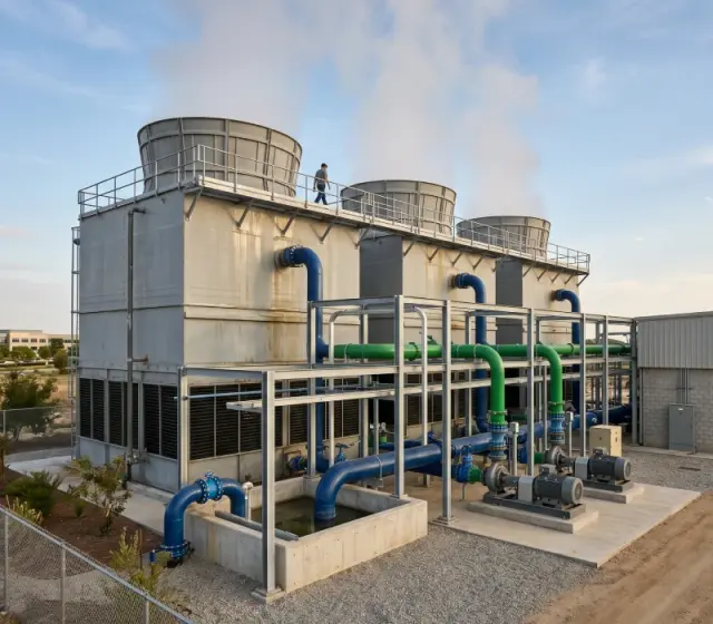
A cooling tower can appear to be operating normally while discharging far more water than necessary. Excessive blowdown increases make-up water demand, chemical consumption, wastewater volume, and the energy required to pump and cool replacement water. Insufficient blowdown creates a different risk: dissolved solids concentrate, causing scale, corrosion, biological growth, and loss of heat-transfer performance.
Cooling tower blowdown optimization is therefore not simply a water-saving exercise. It is a controlled operating strategy that balances water quality, heat rejection, equipment protection, and production reliability. For factories with large process cooling loads, the quality of this balance can influence both utility cost and maintenance planning.
This article explains how industrial plants can evaluate blowdown, calculate the business opportunity, select suitable controls, and avoid the common mistake of increasing cycles of concentration without understanding their water chemistry or operating conditions.
Why cooling tower blowdown deserves engineering attention
Evaporation removes relatively pure water from a cooling tower system, but most dissolved minerals remain in the circulating water. As evaporation continues, the concentration of calcium, magnesium, chlorides, silica, alkalinity, suspended solids, and treatment chemicals rises. Some of these constituents enter with make-up water, while others may be introduced by process leaks, airborne dust, corrosion products, or poorly controlled chemical dosing.
Blowdown removes a portion of the concentrated circulating water. Make-up water then replaces both the evaporated water and the discharged volume. If the blowdown valve is left permanently open, or if it is adjusted conservatively without measurement, the tower may operate at unnecessarily low cycles of concentration.
Low cycles generally reduce the probability of scale formation, but they increase water use and may increase the load on downstream effluent treatment. High cycles reduce make-up water and blowdown volume, but they require closer control of conductivity, hardness, silica, corrosion potential, microbiological activity, and suspended solids.
The objective is not to achieve the highest possible cycles. The objective is to identify the highest stable operating concentration that protects the tower, condenser, heat exchanger, piping, and process equipment under actual plant conditions.
How cycles of concentration affect water consumption
Cycles of concentration describe how concentrated the circulating cooling water is compared with the make-up water. Conductivity is often used as a practical control indicator, although conductivity alone does not describe every scaling or corrosion risk.
For an initial water balance, the main streams are evaporation, blowdown, drift, and make-up. Drift is the small quantity of water carried out of the tower with the air stream. Modern drift eliminators can limit this loss, but their condition and installation still matter. Leakage, overflow, windage, and irregular basin operation may also affect the actual balance.
When cycles are represented as C, a simplified relationship for blowdown is:
Blowdown = Evaporation divided by C minus 1
This simplified expression assumes that drift and other losses are either small or considered separately. The corresponding make-up requirement is approximately the sum of evaporation, blowdown, and drift.
Illustrative example: Assume a cooling tower evaporates 20 cubic metres of water per hour and has negligible drift for an initial comparison. At 3 cycles, the calculated blowdown is approximately 10 cubic metres per hour. At 5 cycles, it falls to approximately 5 cubic metres per hour. The difference is 5 cubic metres per hour, but the practical benefit depends on whether the make-up water chemistry and treatment program can support the higher concentration.
If the tower operates 6,000 hours per year, that difference represents approximately 30,000 cubic metres of water annually in this illustrative case. The actual result may be lower or higher because evaporation, drift, operating hours, leakage, and production load vary. Water and wastewater tariffs should be applied only after the plant has confirmed its measured flow data.
Cooling tower blowdown optimization begins with measurement
Many plants try to reduce blowdown by changing a conductivity set point before establishing the existing water balance. This approach can create confusion because the measured response may reflect a faulty sensor, a leaking valve, fluctuating process load, or inaccurate make-up water flow.
A practical assessment should begin with a short period of reliable baseline measurement. The plant team should record circulating water conductivity, make-up water flow, blowdown flow, basin level, chemical dosing, tower fan operation, wet-bulb conditions, supply and return temperatures, and the operating status of major cooling consumers.
Where possible, the following instruments should be checked or temporarily installed:
- Make-up water flow meter
- Blowdown flow meter or verified valve capacity
- Online conductivity sensor with temperature compensation
- Cooling water supply and return temperature sensors
- Pressure indicators across strainers and filters
- Level measurement in the tower basin or cold-water tank
- Residual biocide or other treatment indicators where applicable
The purpose is not to collect data for its own sake. The data should answer four questions: how much water is entering, how much is leaving, what concentration is being maintained, and whether heat-transfer performance changes when concentration changes.
A conductivity probe should be cleaned, calibrated, and installed where the sample represents the circulating water. Installation near chemical injection points, stagnant branches, or areas with excessive air entrainment can produce misleading readings. A reliable control system cannot compensate for poor sensor location.
What limits the achievable cycles of concentration?
The correct operating limit is determined by the most restrictive water-quality parameter, not by conductivity alone. A plant may have relatively moderate conductivity while still facing a silica or hardness risk. Conversely, a higher conductivity may be acceptable in a system designed with suitable metallurgy, water treatment, filtration, and chemical control.
Scale formation
Calcium carbonate, calcium phosphate, silica, and other deposits can reduce heat-transfer efficiency and restrict flow through heat exchangers. Scale is particularly costly when it forms on process-side cooling surfaces because it increases approach temperature and may force higher flow or fan operation.
Corrosion
Chlorides, low alkalinity, oxygen conditions, incompatible materials, and under-deposit environments can accelerate corrosion. Stainless steel, carbon steel, copper alloys, galvanized components, and elastomers do not respond identically to the same water chemistry. A concentration limit should therefore be reviewed against the actual metallurgy of the system.
Biological activity
Warm, wet cooling systems can support algae, bacteria, and biofilm if treatment and housekeeping are inadequate. Increasing cycles without strengthening monitoring may increase the concentration of nutrients and solids that support deposits or biological fouling. Microbiological control should be treated as a separate engineering requirement rather than assumed to follow automatically from conductivity control.
Suspended solids
Dust, airborne particles, corrosion products, and process contamination can accumulate even when dissolved solids are controlled. Side-stream filtration, basin cleaning, improved air intake management, and better strainers may reduce the need to use high blowdown as a substitute for solids management.
These limitations explain why a plant should not copy a conductivity set point from another facility. Two towers with similar capacities may require different operating limits because their make-up water, materials, chemical programs, heat loads, and ambient conditions are different.
Automatic blowdown control versus manual operation
Manual blowdown can work in a small and stable installation, but it depends heavily on operator consistency and accurate field observation. A manually opened valve may remain in the same position while production load, evaporation rate, make-up water quality, or weather conditions change. The result is often either unnecessary water discharge or delayed response to concentration build-up.
An automatic system normally uses a conductivity transmitter, a controller, and a modulating or on-off blowdown valve. The control logic should include a high-conductivity response, a suitable dead band to prevent rapid cycling, and an alarm for abnormal sensor values. It should also provide a safe response if the transmitter fails or the blowdown valve does not operate.
Automatic conductivity control is valuable, but it is not a complete water-management system. The control philosophy should be coordinated with chemical dosing, filtration, basin level control, make-up isolation, pump operation, and plant shutdown sequences. If a cooling load is removed but the tower fan continues running, evaporation and concentration behaviour may change. If the basin is drained during maintenance, the conductivity signal may not represent normal operation when the system restarts.
For larger plants, a supervisory control and data acquisition system can trend conductivity, make-up, blowdown, temperatures, and alarms. This makes it easier to identify slow drift, abnormal water losses, and seasonal changes. Enercon Worldwide can evaluate industrial utility systems as part of an integrated engineering assessment, where cooling water performance is reviewed alongside pumping, process heat, water treatment, and plant operating requirements.
Where water savings can be lost
Improving cycles of concentration may produce little net benefit if other losses remain uncontrolled. A tower that saves water through automatic blowdown but loses water through overflow, leaking valves, damaged fill, or an incorrectly configured level-control system has not achieved genuine optimization.
Common field checks include inspecting the basin overflow, make-up valve seat, blowdown valve, pump mechanical seals, flange joints, distribution headers, drift eliminators, and nearby drains. The plant should also compare the theoretical water balance with actual make-up meter readings. A persistent difference is a signal to investigate, not an accounting inconvenience.
Drift eliminators deserve specific attention. Damage, poor fit, fouling, or excessive air velocity can increase water carryover and may affect nearby structures or equipment. A high drift rate also weakens the expected water-saving benefit of improved cycles.
Heat-transfer performance must be tracked at the same time. Useful indicators include cooling-water supply temperature, return temperature, process outlet temperature, approach temperature, pump pressure, fan status, and the availability of critical cooling users. Water reduction that causes a higher process temperature or unstable production is not a successful optimization.
Illustrative financial evaluation
A financial review should include water, wastewater, chemicals, pumping, maintenance, and any effect on production reliability. It should not count the full value of reduced blowdown as savings if the discharged water is recycled elsewhere or if additional chemical treatment offsets the reduction.
Illustrative example: Consider a plant that reduces blowdown by 5 cubic metres per hour after confirming that its cooling-water chemistry remains within an approved operating envelope. Assume 6,000 operating hours per year. The annual water volume reduction would be approximately 30,000 cubic metres.
If the combined purchased-water and discharge cost is assumed for illustration to be 1.20 currency units per cubic metre, the direct volume-related value would be 36,000 currency units per year. If chemical consumption, pumping energy, or instrumentation adds a further verified benefit, those values can be included separately. If the project requires 18,000 currency units for a conductivity controller, valve, flow measurement, installation, and commissioning, the simple payback based only on the illustrative water value would be about six months.
This is not an industry benchmark or an Enercon project result. Actual payback depends on local tariffs, treatment costs, operating hours, equipment prices, existing instrumentation, water chemistry, and whether the tower can operate safely at the proposed concentration. A technically attractive project can have a longer payback when water is inexpensive, while a modest flow reduction can be valuable where water supply or effluent capacity is constrained.
Application in process industries
Cooling tower optimization is especially relevant to plants with continuous heat loads and long annual operating schedules. Chemical facilities may use cooling water for reactors, condensers, compressors, and heat exchangers, where a temperature increase caused by fouling can affect process control. Food and beverage facilities may have several cooling users with different operating patterns, making load measurement important before selecting a common control strategy.
In steel, cement, and metal-processing facilities, cooling systems may serve furnaces, hydraulic equipment, rolling systems, compressors, or auxiliary machinery. Suspended solids, dust ingress, and high ambient temperatures can be more significant than dissolved solids alone. Side-stream filtration and basin housekeeping may therefore deliver more reliable results than simply reducing blowdown.
Pharmaceutical and specialty chemical plants may place greater emphasis on material compatibility, cleanability, validated operating procedures, and segregation between process and utility circuits. A cooling-water modification should be reviewed for its effect on critical equipment and plant quality procedures.
In all sectors, the utility team should map each cooling loop rather than assume that one set point is suitable for every circuit. A closed secondary loop, an open evaporative tower, and a once-through or treated process-water circuit have different control requirements.
Retrofit checklist for a reliable project
Before approving cooling tower blowdown optimization, the project team should complete a practical feasibility review.
- Confirm the current make-up and blowdown volumes using measured data.
- Test and document make-up water chemistry, including hardness, alkalinity, chlorides, silica, pH, and conductivity where relevant.
- Review the metallurgy and condition of cooling towers, heat exchangers, piping, pumps, and valves.
- Identify the parameter that will set the operating limit, rather than relying on conductivity alone.
- Verify chemical-treatment compatibility at the proposed concentration range.
- Check sensor location, calibration method, sample flow, and maintenance access.
- Provide alarms and manual override provisions for sensor or valve failure.
- Measure process temperatures before and after the change.
- Confirm how blowdown is routed and whether the effluent system can accept changes in flow or concentration.
- Train operators to interpret trends and investigate abnormal readings.
The vendor or engineering partner should also explain how the system will behave during start-up, shutdown, low-load operation, basin cleaning, chemical dosing interruptions, and loss of make-up water. These operating cases often determine whether an automatic system remains dependable after commissioning.
Making the decision from plant data
The most defensible improvement program combines water balance, chemistry review, equipment inspection, and operating data. A plant should first establish its present cycles and losses, then identify the limiting water-quality parameter, and finally compare control options.
For some facilities, the best project will be an automatic blowdown controller. For others, it may be side-stream filtration, drift-eliminator replacement, basin cleaning, chemical-program correction, heat-exchanger maintenance, or separation of cooling loops. Increasing cycles is only one tool within a broader cooling-system strategy.
Enercon Worldwide can support industrial utility evaluations that connect cooling performance with water treatment, pumping, process requirements, and control integration. The practical next step is a site data review covering at least representative operating conditions, followed by a measured water balance and a risk-based operating limit.
When cooling tower blowdown optimization is treated as an engineering control problem rather than a valve-adjustment exercise, the plant can pursue lower water consumption without trading away heat-transfer reliability, asset life, or production stability.
Related Enercon solutions
Planning an energy or utility project? Talk to the engineers at Enercon Worldwide or request a consultation. You can also browse all our business areas.